My Cosmac 1802 build
Back in 1976 Popular Electronics published an article about an RCA CPU called CDP1802, COSMAC ELF.
This was to be the entry point to computers for me.
Had fun building it on a perf board and point to point wire soldering.

Below my collection of "1802 bibles". Each one of these magazines had 1802 projects/ programs/ or schematics.

Fast forward some 4 decades and now I'm re-visiting that humble little computer and super sizing it a bit.
Here is my latest incarnation the Steam Punked COSMAC VIP - ELF project.

What is it? Its made up of 5 parts, The MAIN cabinet, The Glass TUBE Display, The BCD-HEX keyboard, The ROTARY HEX keyboard and Audio Speaker (horn), and finally the VIDEO CRT display unit.
The main electronics are made up of custom made PCB 4" x 4" stacked on a 5" x 10" motherboard.
They are located in the MAIN cabinet, ( the unit with the 8 blue 7 segment VFD displays).


Main Cabinet, Salvaged from an old tube radio, I re purposed the wood, added hinges to the lid, used the brass face plate from another old tube receiver. Added 8 VFD "nixie" 7 segment display tubes, a few push buttons from an older oscilloscope, a numerical Nixie tube, a a few lights for bus activity, CPU status and a Magic Eye glass tube for the audio aka Q line.


GENERAL OVERVIEW
Below is a short video 43 sec in length, showing a simple BEEPER program, The Magic EYE working, the BCD keyboard and the Glass tube display.
You should hear the audio beep , this was a "test program" from the ELF, the toggle switches altered the speed of the tone bursts
Inside look, lid up.


In the above view, foreground is the main cabinet, to the right of it is the Rotary Hex keyboard ( big brass dial ) looking thingy, below that unit is the dual BCD/ Hex VIP keyboards, (typewriter style keys).Directly behind the main cabinet is the Glass Tube display unit ( has the RED RCA Victrola and Nipper plaque)

DISPLAYS
VFD display PCB, group of 4 VFD on the right are ADDRESS, 2 in the center are DATA, the 2 on the far left are what I call PRE-DATA. Pre-data is what the ROTARY or BCD switches are selected at, they will be transferred to the DATA bus only when INPUT switch is depressed.


above pic, Purple glow is from RGB leds .

above, typical of 8 Hex LED test tube displays, socket pins are from salvaged TV tubes, cut and fitted to test tube. Custom made 16 led pcb, with 74HC154 smt on backside. 4 to 16 decoder.
Video 32 sec, of 1Test tube chase test pattern , 5 Neo pixels in each base socket chase pattern.

Above is a photo of the metal chassis cover with tubes from an RCA radio (not the one I "cut up")

Above is my donor chassis cover plate, pre-polished as a test before been cut.

Above is a test fit up. This display unit is made up of brass rail tube, candelabra light bulb socket holders ( light sockets removed), antique window braces, glass tray, base is cut from 1" thick black solid material routed edges and polished, not visible is a routed grove underneath housing the RED led tape lights


the final product, polished and lit up.
Keyboards
33 sec video of HEX ROTARY keyboard unit, notice at the 20 second mark the rotation of the 4 copper timing disks, look closely and you can see the Photo transistor switches, ABCD hex, and finally at the end of the video the large brass dial, was turned from a 1/2" plate, then acid etched to make the numerics 0 to F, and segments. (see next 44 seconds video of brass dial )

Above is the final look, at the top is the SPKR/ horn, next below is the Rotary HEX dial keyboard, below on the bottom is the Dual HEX ( aka the toggle switches on the original ELF), and on the botom botom is the VIP hex keyboard PB switches ( typewriter keys). You can't see very well in this photo but there is an RCA medallion in the center of the rotary knob/ dial.
The pics below show the printed pattern (laser) , then transferred to brass plate, and then etched and polished.

Making of the RCA Medallion for the rotary dial knob center

Final product, medallion etches, polished, and cut, ready to be installed.

Above you can see the RCA logo medallion and one of the other brass connector plates. You can see the outline for the DB connectors and the DIN connector. The outer rectangular box (lines) are my cut up to template.
Above is a 44 seconds video of transferring laser printed dial segments to the brass dial knob, getting it ready for the etchant bath.


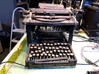
Donner radio cabinet for lower Hex toggle switches and VIP keyboard. ( typewriter)


here you see the addition of the "organ" keyswitches in place. 4 grey, 4 white.


cabinet before staining

Stained and now has foot rest for Rotary keyboard unit in place, black strips running on the top sides. white LEDS also in place on "toggle switches"

above photo shows brass etching of CHIP8 commands, 0= Ram Write, A= Ram Read, B= Tape Read, F= tape Write.

installation location on base

Front view with brass plaque in place.


Above, Far left bottom is the MAIN cabinet, sitting on its lid is the "test tube" display, in the center are the 3 KEYBOARDS , to the far right is the VIDEO unit (crt) , some might have notices the CRT shown here has only 1 CRT , later version has 2 CRT displays, as shown in the next few photos/ videos.
Video 56 seconds , Laser toner transfer to brass example
Video 70 seconds, Toner paper removal with water.
Video Monitor

Rear view of Video (left) and Keyboard units (right), notice the DUAL CRTs on the video unit. a smaller 2" and a 4" CRT. The 2" crt is from a Sony Watchman TV, the 4" crt is from a video door intercom. All the electronics are housed in the Video units base cabinet. A DB15HD connector supplies Video, Power and switch functions. There is also a Composite video OUT RCA connector.

Front view of Video unit, 2 CRTs.
Software Load example
Video 1:22 seconds with audio, demo of Software load from cassette.
Video short 17 seconds Star ship scroll.
Video short 6 seconds Snoopy
Video 1:25 seconds long, Talking / voice example. ( audio is not very loud, I will re-do in the future.)
Project more to come later. Ver 1.0 last update Oct 13 10:15 am

Comments
Post a Comment